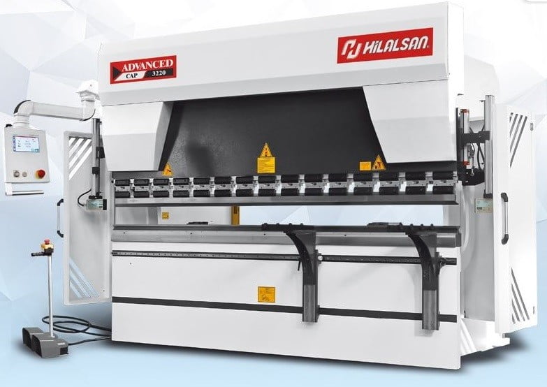
CNC Press Brake ADVANCED - Hilalsan

General features
- The machine frame is manufactured with advanced technology with very precise tolerances and stress relieved with large welded components. All tensile points are designed with large radii and strain accumulation and possible welding cracks are eliminated.
- The lower and upper tables’ inertias are designed for optimum value for minimum deformation..
- The top plate is designed to be positioned vertically so that the roller bearings, piston bearings and felts can compensate for vertical loads.
- The hydraulic cylinder is designed as double-sided and honed to a surface quality of 2 microns. Thus, minimum wear resistance is created
- for the felts. The cylinder bodies are manufactured as SAE 1040 material forged.
- The hydraulic cylinders are bolted to the front of the feet with bolts and cams to provide excellent leveling and load balancing.
- Piston head features: Omega-type felts are ftted with wide bronze bearings, semi-angled sleeves.
- The pistons are precision ground and hard chrome plated to provide low friction and abrasion resistance when the piston passes through the felts.
- The adjustable top tray slides are made from materials that are suitable for very low friction resistance. These beds are arranged for guiding to move the top table from right to left and front to rear.
- The Hilalsan hydraulic system allows precise usage at all pressure values up to the maximum operating pressure. At the same time, with these pressure values, precise cylinder positioning, synchronization and repeatability are achieved.
- Backgauge system is manufactured in accordance with environmental conditions. Backgauge bearings are made for heavy conditions
- with double bearers. Scrapping type bearings are used against dust and other particles that will accumulate in the linear guideways against dusty environmental conditions.
- The outer surface of the machine is painted with two layers of paint at least 60 microns in thickness to protect against weather conditions. Paint drying is done gradually in different time and temperature ranges in state-of-the-art ovens.
- Standart Y1, Y2, X axis.
| CAP Machine Type |
X Axis Speed |
R Axis Speed |
Travel in R-axis |
Travel in X-axis | Motor Power |
Oil Capacity |
Length | Width | Height | Approximate Weight |
||
| 500 | 750 | 1000 | ||||||||||
| mm/sn. | mm/sn. | mm | mm | mm | mm | Kw | Lt | mm | mm | mm | Kg | |
| L | W | H | ||||||||||
| 1360 | 250 | 100 | 200 | S | — | Op. | 5,5 | 100 | 2150 | 1500 | 2300 | 3800 |
| 2060 | 250 | 100 | 200 | S | — | Op. | 7,5 | 100 | 3050 | 1650 | 2350 | 4500 |
| 26100 | 250 | 100 | 200 | S | — | Op. | 11 | 250 | 3400 | 1850 | 2650 | 7000 |
| 3100 | 250 | 100 | 200 | — | S | Op. | 11 | 250 | 3900 | 1950 | 2750 | 7800 |
| 3135 | 250 | 100 | 200 | — | S | Op. | 15 | 250 | 3900 | 1950 | 2800 | 9000 |
| 3175 | 250 | 100 | 200 | — | S | Op. | 18,5 | 250 | 3900 | 2000 | 2850 | 10000 |
| 3220 | 250 | 100 | 200 | — | S | Op. | 22 | 250 | 3950 | 2000 | 2900 | 12000 |
| 3270 | 250 | 100 | 200 | — | S | Op. | 22 | 350 | 3950 | 2000 | 2950 | 13000 |
| 3320 | 250 | 100 | 200 | — | S | Op. | 30 | 350 | 4000 | 2250 | 3150 | 14500 |
| 3400 | 250 | 100 | 200 | — | S | Op. | 37 | 350 | 4050 | 2250 | 3250 | 18500 |
| 37175 | 250 | 100 | 200 | — | S | Op. | 18,5 | 250 | 4550 | 2000 | 2900 | 11500 |
| 37220 | 250 | 100 | 200 | — | S | Op. | 22 | 250 | 4550 | 2000 | 3000 | 13500 |
| 37320 | 250 | 100 | 200 | — | S | Op. | 30 | 350 | 4600 | 2250 | 3200 | 18000 |
| 4175 | 250 | 100 | 200 | — | S | Op. | 18,5 | 250 | 4950 | 2000 | 2900 | 12000 |
| 4220 | 250 | 100 | 200 | — | S | Op. | 22 | 250 | 4950 | 2000 | 3000 | 15000 |
| 4270 | 250 | 100 | 200 | — | S | Op. | 22 | 350 | 4950 | 2000 | 3000 | 17500 |
| 4320 | 250 | 100 | 200 | — | S | Op. | 30 | 350 | 5000 | 2250 | 3200 | 20500 |
| 4400 | 250 | 100 | 200 | — | S | Op. | 37 | 350 | 5000 | 2250 | 3300 | 25000 |
| 6220 | 250 | 100 | 200 | — | S | Op. | 30 | 350 | 7000 | 2000 | 3350 | 24000 |
| 6320 | 250 | 100 | 200 | — | S | Op. | 30 | 350 | 7000 | 2250 | 3500 | 28000 |
| 6400 | 250 | 100 | 200 | — | S | Op. | 37 | 500 | 7050 | 2250 | 3700 | 35500 |
| 6600 | 250 | 100 | 200 | — | S | Op. | 45 | 500 | 7200 | 2650 | 3900 | 54000 |
| 6800 | 250 | 100 | 200 | — | S | Op. | 55 | 650 | 7200 | 3100 | 4200 | 70000 |
| 61000 | 250 | 100 | 200 | — | S | Op. | 55 | 650 | 7400 | 3250 | 4500 | 78000 |
| 61250 | 250 | 100 | 200 | S | Op. | 90 | 650 | 7400 | 3300 | 5300 | 97000 | |
|
CAP |
Bending Force |
Bending Length |
Distance between columns |
Stroke | Daylight | Throat depth |
Table Height |
Pit Depth |
Table Width |
Y Rapid Speed |
Y Working speed |
Y Return speed |
| Ton | mm | mm | mm | mm | mm | mm | mm | mm | mm/sn. | mm | mm/sn. | |
| A | B | C | D | E | F | T | G | |||||
| 1360 | 60 | 1300 | 1100 | 185 | 390 | 310 | 850 | — | 108 | 140 | 10 | 130 |
| 2060 | 60 | 2100 | 1700 | 185 | 390 | 310 | 850 | — | 108 | 140 | 10 | 130 |
| 26100 | 100 | 2600 | 2200 | 205 | 410 | 310 | 900 | — | 108 | 130 | 10 | 130 |
| 3100 | 100 | 3100 | 2600 | 265 | 480 | 410 | 900 | — | 108 | 130 | 10 | 130 |
| 3135 | 135 | 3100 | 2600 | 265 | 480 | 410 | 900 | — | 108 | 130 | 10 | 130 |
| 3175 | 175 | 3100 | 2600 | 265 | 480 | 410 | 900 | — | 108 | 130 | 10 | 120 |
| 3220 | 220 | 3100 | 2600 | 265 | 480 | 410 | 900 | — | 108 | 120 | 10 | 100 |
| 3270 | 270 | 3100 | 2600 | 265 | 480 | 410 | 950 | — | 108 | 110 | 9 | 100 |
| 3320 | 320 | 3100 | 2600 | 315 | 530 | 510 | 950 | — | 154 | 100 | 9 | 90 |
| 3400 | 400 | 3100 | 2550 | 315 | 530 | 510 | 950 | — | 154 | 90 | 8 | 80 |
| 37175 | 175 | 3700 | 3200 | 265 | 480 | 410 | 950 | — | 108 | 120 | 10 | 100 |
| 37220 | 220 | 3700 | 3200 | 265 | 480 | 410 | 1000 | — | 108 | 110 | 10 | 100 |
| 37320 | 320 | 3700 | 3200 | 315 | 530 | 510 | 1000 | — | 154 | 90 | 9 | 90 |
| 4175 | 175 | 4100 | 3600 | 265 | 480 | 410 | 950 | — | 108 | 120 | 10 | 100 |
| 4220 | 220 | 4100 | 3600 | 265 | 480 | 410 | 1000 | — | 108 | 100 | 9 | 100 |
| 4270 | 270 | 4100 | 3600 | 265 | 480 | 410 | 1000 | — | 108 | 100 | 8 | 80 |
| 4320 | 320 | 4100 | 3600 | 315 | 530 | 510 | 1000 | — | 154 | 90 | 8 | 80 |
| 4400 | 400 | 4100 | 3550 | 315 | 530 | 510 | 1000 | — | 154 | 90 | 8 | 80 |
| 6220 | 220 | 6100 | 5100 | 265 | 480 | 410 | 1150 | — | 154 | 80 | 8 | 80 |
| 6320 | 320 | 6100 | 5100 | 315 | 530 | 510 | 1150 | — | 154 | 80 | 8 | 80 |
| 6400 | 400 | 6100 | 5100 | 315 | 530 | 510 | 1200 | — | 240 | 70 | 8 | 60 |
| 6600 | 600 | 6100 | 5100 | 365 | 580 | 510 | 1000 | 700 | 240 | 70 | 7 | 70 |
| 6800 | 800 | 6100 | 5100 | 415 | 630 | 610 | 1000 | 900 | 400 | 70 | 6 | 60 |
| 61000 | 1000 | 6100 | 5100 | 515 | 730 | 610 | 1050 | 1050 | 400 | 70 | 5 | 60 |
| 61250 | 1250 | 6100 | 5100 | 515 | 730 | 610 | 1050 | 1200 | 400 | 70 | 5 | 60 |